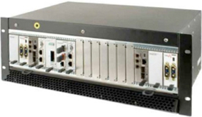
In order to reduce capital expenditures (CAPEX) for LTE operators, most equipment vendors are developing LTE eNBs using generic, “off the shelf” platforms such as ATCA, Micro-TCA, and AMC in PICMG. Proprietary platforms have been used until the 3G/3.5G network era. The Micro-TCA platform (see image) is one of the most powerful options for telecom equipment applications, especially for use with LTE eNBs. Many component vendors are developing modules based on general purpose Micro-TCA modules with powerful CPUs, DSPs, and FPGAs, as well as high speed memory and Gigabit Ethernet (GbE) interface on the front side. Each module in the chassis can communicate with not only the GbE interface as the control interface from the server module, but also with the 10 Gbps Serial Rapid I/O (sRIO) interface. Micro-TCA Connection Handler (MCH) modules enable star topology on the backplane, switching the packets from all modules on the platform. 10 GbE is selectable for this start topology connection on Micro-TCA.
Figure 1 : MicroTCA platform
The sRIO interface is used for connections between the Uu-side baseband module and the S1/X2-side network I/F module. The baseband functions and network interface functions are usually implemented on different modules, and connected with an sRIO I/F over the MCH. Most equipment developers use FPGAs for PHY/Baseband, DSPs or Network processors for Lower layer protocols (HARQ/MAC/RLC), and CPUs or Network processors with operation system for PDCP and upper layers, as shown in the table below.
LTE eNB Implementation Example
| Function | Implementation |
|---|---|
| PHY/ Baseband | FPGAs/ASSPs |
| Lower layer protocol | DSPs/Network processor |
| PDCP and upper layer protocols | CPUs/Network processor with operation system |
eNodeB vendors can minimize their development efforts by using generic components, not only in terms of hardware modules but also in terms of intellectual property like baseband logical circuits on FPGAs, protocol stack software, etc. The figures below show examples of LTE eNB implementation on a Micro-TCA platform.
Figure 2 : LTE eNB implementation example (C-plane)
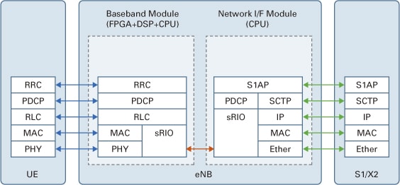
Figure 3 : LTE eNB implementation example (U-plane)
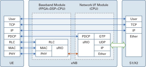
Figure 4 : LTE eNB implementation on MicroTCA platform
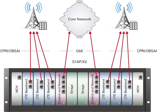
The diagram above shows an example of an eNB implementation that connects two eNBs covering six sectors over two cells. The eNB is connected to the S1/X2 with two GbE interfaces.