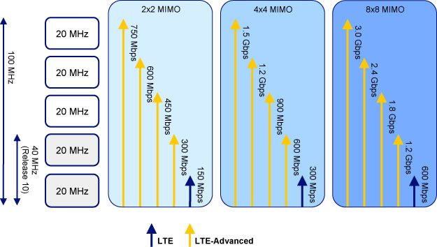
LTE-Advanced comprises an array of new technologies, as shown in Figure 1, but the two key technologies for boosting UL/DL speeds are Multiple Input Multiple Output (MIMO), and Carrier Aggregation (CA). Working in combination, these technologies will dramatically increase the effective bandwidth, providing enhanced communication performance and enabling potential max downlink speeds up to 3Gbps, as shown in Figure 2.
Figure 1 : New Technologies in LTE-Advanced
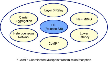
Figure 2 : DL Acceleration with CA and MIMO
Carrier Aggregation
Carrier Aggregation (CA) is an innovative approach to create wider bandwidth by using multiple aggregated Component Carriers (CCs). LTE Rel. 10 adopts the CA technique to increase spectral bandwidth up to 100 MHz using multiple CCs as shown in Figure 3. The aggregated CCs must be on compatible spectral bandwidth supported by LTE Rel. 8 (i.e. 1.4 MHz/3 MHz/5 MHz/10 MHz/15 MHz/20 MHz). It allows seamless migration into LTE Rel. 10 by re-utilizing LTE Rel. 8 eNBs along with standards for radio frequencies (Figure 3), Adjacent Channel Leakage Ratio (ACLR), Spectrum Emission Mask (SEM), Adjacent Channel Selectivity (ACS) and blocking.
As LTE Rel. 10 UEs are backwards compatible with LTE Rel. 8 standards, the CA provides the advantage of reducing redundant implementation. An LTE Rel. 10 UE that is CA-enabled would achieve higher user throughput than an LTE Rel. 8 UE.
There are three types of CA, depending on the CC combination as shown in Figure 4.
Figure 3 : Carrier Aggregation
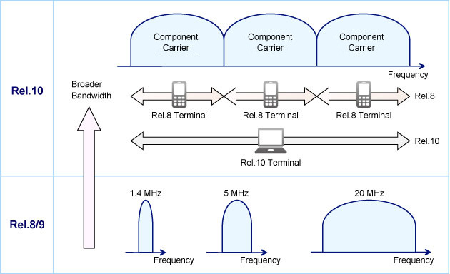
Figure 4 : Three Types of Carrier Aggregation
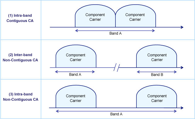
1. Intra-band Contiguous CAContiguous bandwidth wider than 20 MHz is used in this scenario. For example, wideband such as the 3.5 GHz band would fit this model.
2. Inter-band Non-contiguous CANon-contiguous bandwidth over multiple bands is used in this scenario. Networks with two spectrum bands (e.g., 2 GHz and 800 MHz) would fit this model. This scenario has the advantage of achieving higher throughput simply by using two carriers, while also improving transmission stability by using two different spatial paths on different spectrum bands.
3. Intra-band Non-contiguous CAThis scenario uses non-contiguous bandwidth in the same band. This model would fit operators in North America or Europe, who use fragmented spectrum in one band or share the same cellular network.
CA Deployment ScenariosThere are four possible CA Scenarios for real LTE-Advanced deployment.
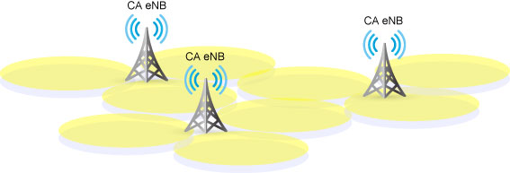
(a) Multiple CCs over contiguous bandwidth (Figure 5).Figure 5 : Overlapped Coverage
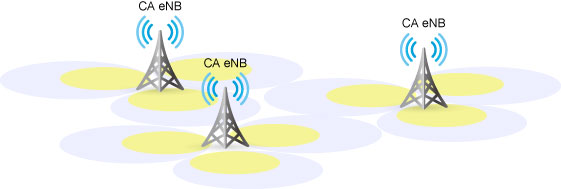
(b) CCs over different bands with different coverage in cells (Figure 6).Figure 6 : Different Coverage
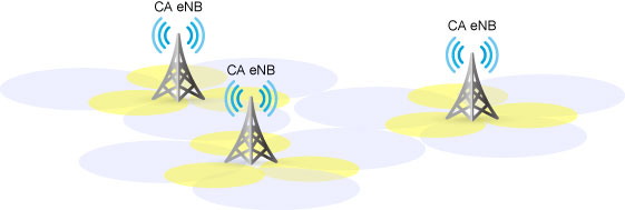
(c) CCs cover cell edges of different CC cells (Figure 7).Figure 7 : Cell Edge Beamforming
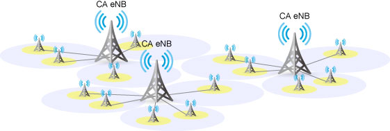
(d) Macro coverage with lower CC and Hotspots with RRH (Remote Radio Heads) (Figure 8).Figure 8 : RRH Integration
New MIMO Techniques
LTE Rel.8 supported up to 4-layer downlink MIMO and no uplink MIMO. LTE-Advanced supports Single-User MIMO (SU-MIMO) schemes up to 8-layer downlink MIMO (8x8 MIMO) and 4-layer uplink MIMO (4x4 MIMO). Using this technology, networks can achieve a peak spectral efficiency of 30 bit/s/Hz for downlink and 15 bit/s/Hz for uplink. In other words, 20MHz of bandwidth can achieve up to 600 Mbps downlink speed.
Figure 9 : Closed-Loop MIMO (4x4 MIMO Rank-2)
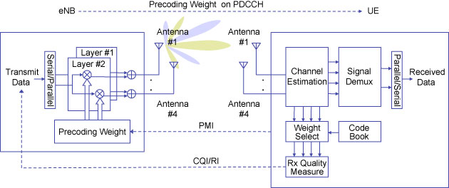
Figure 10 : Rank Adaptation
Multi-user MIMO (MU-MIMO) is another important technology for increasing peak data rates, system capacity, and cell edge user throughput. MU-MIMO and CoMP transmission, described below, apply various advanced signal processing techniques such as beamforming, adaptive transmission power control, and multi-cell simultaneous transmission.
CoMP Techniques
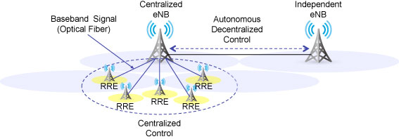
Coordinated Multi-Point transmission/reception (CoMP) is a DL/UL technique for improving system capacity and cell edge user throughput. Currently, there are two different approaches for CoMP (Figure 1). One approach uses autonomous, decentralized control and an architecture with independent eNBs. The second approach uses centralized control and an architecture based on Remote Radio Equipment (RRE).
In the approach with independent eNB architecture, CoMP is performed by signaling between eNBs. This technique can utilize legacy cells, but the disadvantages include signaling delay and other overheads.
In the second approach that integrates RRE, the eNB can centralize and control all radio resources by transmitting baseband data directly between the eNB and RRE on optical fiber connections. There is little signaling delay or other overheads in this technique, and intra-cell radio resource control is relatively easy. However, optical fibers may require significant CAPEX, and the central eNB must be able to handle higher loads according to the number of RRE. Therefore, both approaches are under consideration for LTE-Advanced.
Figure 11 : Centralized/Autonomous Decentralized Control
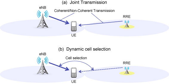
Downlink CoMPDownlink CoMP also has two approaches under consideration for LTE-Advanced: Coordinated Scheduling/Beamforming (CS/CB) (Figure 2), and Joint Processing (Figure 3).
In CS/CB, transmission to a single UE is performed by the serving cell, just as in non-CoMP transmission. However, the scheduling of transmissions is dynamically coordinated between the cells, including any beamforming functionality. In that way, the interference between different transmissions can be controlled and reduced. In principle, schedule optimization will be based on the set of users being served, so that the transmitter beams are constructed to reduce interference with other neighboring users while increasing the served users’ signal strength.
In Joint Processing, the Joint Transmission scheme transmits data to a single UE simultaneously from multiple transmission points. The multi-point transmissions will be coordinated as a single transmitter with multiple antennas that are geographically separated. This scheme offers potentially higher performance gains compared to CS/CB, but also places a high signaling overhead on the backhaul network.
Figure 12 : Downlink CoMP 1

Figure 13 : Downlink CoMP 2
Uplink CoMPUplink CoMP uses geographically separated antennas for receiving signals from UEs, and scheduling decisions are coordinated by multiple cells to control interference. The UE is not aware that multiple cells are receiving its signal, so the impact on radio interface specifications is minimal. Implementation of uplink CoMP largely depends on the scheduler and receivers in the cells.