

Resources
O-RAN Load and Stress Tests
Artiza Networks provides scalable Load and Stress Test solutions
Performance evaluation of 4G eNodeBs and 5G gNodeBs has traditionally centered around basic functional and performance testing. Functional tests usually evaluate how well eNBs or gNBs execute basic sequences a specified number of times such as attach/detach, registration/deregistration, and how they handle various levels of UE mobility. Performance tests are mainly used to check user data (U-Plane) throughput.
In these types of tests alone, however, there are no test items for the real-world traffic load that the eNB/gNB may experience in the field. This raises a concern that the eNB/gNB and its functions for call control processing may be insufficient to handle all the traffic that can occur on actual commercial networks.
In order to comprehensively evaluate all the functions, performance, and capacity of a base station, a number of tests specific to each function of the eNB/gNB are required. It is recommended to use a dedicated load tester in addition to the function tester and performance tester described above to perform these tests.
Artiza Networks decided to join the O-RAN ALLIANCE and actively contribute to the Test and Integration Focus Group (TIFG). Artiza has accumulated expertise in load and stress testing methods for mobile base stations since the days of 3G and 4G networks. TIFG is a focus group of the O-RAN ALLIANCE that deals with the standardization of testing and evaluation methods for 5G and O-RAN supporting devices.
In TIFG, Artiza Networks contributed to the study of evaluation methods for load and stress testing of eNB/gNBs along with other contributors. After rounds of intensive discussions among the contributors involved, the results have been officially documented in Chapter 8: Load and Stress Tests in O-RAN.TIFG.E2E-Test.0-v 2.00 published by O-RAN ALLIANCE.
In this chapter, the following 8 test cases are discussed. This website provides an overview of each test case. For detailed test procedures, please refer to the above document published by O-RAN ALLIANCE.
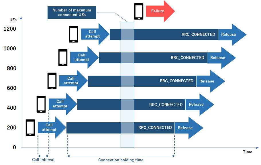
The first step in verifying the load capacity of eNBs/gNBs uses a UE simulator to simulate UEs in the RRC_CONNECTED state of the Radio Resource Control (RRC) protocol, which is the C-plane protocol between the UE and the eNB/gNB. This step measures the maximum number of UEs that the eNB/gNB can connect and maintain simultaneously.
RRC is the protocol defined by 3GPP TS 38.331(NR) and TS 36.331 (LTE) which controls radio resources in RANs such as system Information, connection control, mobility, and Measurement.
Call loss may start to occur when the allowable number of UEs is exceeded due to insufficient radio resources and/or insufficient memory in the software of the call control unit. By connecting multiple UEs at the same time, the gNB’s capacity can be verified.
Since this test requires a large number of simulated UEs, it requires high scalability in the number of UEs that can be simulated.
The figure below shows how the Simultaneous RRC_CONNECTED UEs test works.
Figure 1
How the Simultaneous RRC_CONNECTED UEs test works
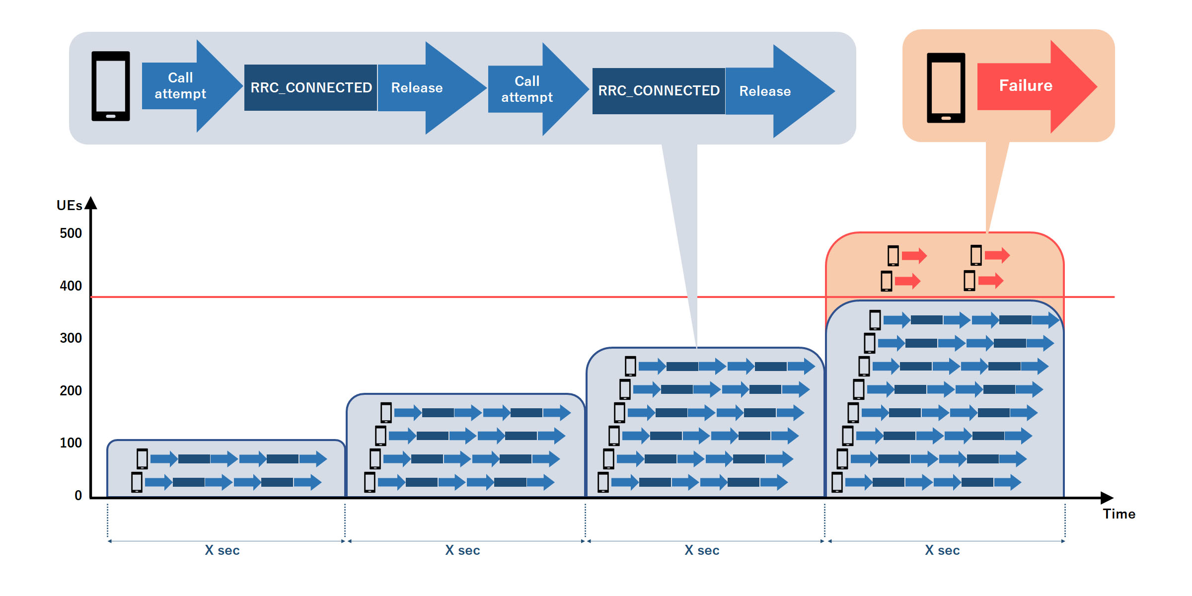
The difference between this test and the Simultaneous RRC_CONNECTED UEs test is that, as shown in the title, the RRC state in the C-plane transitions between _IDLE and _CONNECTED continuously within a certain period of time, and the number of simulated UEs will be increased.
The test procedure is to gradually increase the number of connected UEs by using the UE simulator. Further, the UEs alternate between RRC_CONNECTED state and RRC_IDLE state. By performing tests while changing the state of the UEs, it is possible to test performance under conditions where more processing load is applied to the eNB/gNB.
If the number of UEs exceeds a certain number, the point at which call loss occurs (i.e., benchmark) can be identified.
This test, as in the previous test, requires simulating a large number of UEs with a UE simulator. The UE simulator used must be highly scalable.
The figure below shows how the Benchmark of UE State Transition Simultaneous RRC_CONNECTED UEs test works.
Figure 2
How the Benchmark of UE State Transition Simultaneous RRC_CONNECTED UEs test works
To verify the basic gNB C-plane processing capability by connecting multiple UEs with state transitions which will cause more burden in C-plane processing than just one RRC_CONNECTED state
While the previous two test cases are intended to test the C-Plane processing capacity of the eNB/gNB, this test case verifies stability with U-Plane traffic. The purpose of this test is to verify the stability of the eNB/gNB under high load while a large number of simulated UEs send and receive (via a UE simulator) user data on the U-plane. Maximum cell throughput is covered in another chapter in the same O-RAN O-RAN.TIFG.E2E-Test.0-v 2.00 document published by O-RAN ALLIANCE, so it will not be discussed in this chapter.
The test procedure is to connect X number of UEs (e.g. 10UEs) per second to the eNB/gNB with UDP download/upload traffic on U-plane, then continually increase the number of UEs until it reaches N number of connected UEs (e.g. 1,000UEs). Once N is reached, start disconnecting X number of UEs per second and connecting X number of new UEs to the eNB/gNB, also with UDP download/upload traffic. By continuing to disconnect and connect UEs, and by connecting UEs near the maximum number, the test can verify the stability of the eNB/gNB.
Performing this requires the ability to deploy large numbers of UEs simulated by the UE simulator until reaching 1,000 UEs. As in the previous tests, a scalable and stable UE simulator is required.
This test case involves traffic models and defined traffic model types, which are described in the tables below.
In actual field communications carried out by mobile terminals, the amount of traffic can vary significantly depending on the regional characteristics of where the base station is or will be located. Variable factors include the attributes and types of UEs, the number of UEs, the amount of UE mobility, and even the time of day. These different traffic patterns will be referred to as traffic model types, and an excerpt of some of the traffic model types described in the O-RAN ALLIANCE document is shown in the table below.
Table 1: Example of typical traffic model types
| No. | Traffic Model Type | Major Characteristics |
|---|---|---|
| 1 | Indoor Hotspot |
|
| 2 | Dense Urban |
|
| 3 | Office Area |
|
| ... | ... | ... |
An appropriate traffic model must be developed that accounts for the maximum number of UEs expected in the target area and their expected behavior in the field. The test procedure is to use a UE simulator to simulate various UE behaviors such as attach/detach, registration/deregistration, data upload/down, mobility, etc. An example traffic model is shown in the table below.
Table 2 : Example of Traffic Model
| No. | Scenario (baseline) | LTE | 5G NSA |
5G SA |
Number of UEs |
Attempts (per UE per hour) |
Description |
|---|---|---|---|---|---|---|---|
| 1 | Attach | ○ | ○ | N/A | 50 | 0.50 | Power ON |
| 2 | Detach | ○ | ○ | N/A | 50 | 0.50 | Power OFF |
| 3 | Tracking area update | ○ | ○ | N/A | 100 | 1.00 | |
| 4 | Registration | N/A | N/A | ○ | 50 | 0.50 | Power ON |
| 5 | Deregistration | N/A | N/A | ○ | 50 | 0.50 | Power OFF |
| 6 | Paging | ○ | ○ | ○ | 200 | 1.00 | Total of paging in this model |
| ... | ... | ... | ... | ... | ... | ... | ... |
The traffic model must fully consider the regional environment in which the base station will be located and determine the traffic model type and traffic type characteristics likely to be encountered. The test can deploy one or more traffic models to evaluate the capacity, stability, and load tolerance of the eNB/gNB in the lab, thus verifying eNB/gNB performance under representative traffic loads that may occur in the field.
Prior to commercial deployment, validate gNB performance in the lab by simulating the complex traffic models that gNB may actually experience in the field
This test evaluates the stability of the base station over dozens of hours in each scenario by repeating call generation and call release using various traffic patterns.
This type of testing requires performing tests with various traffic model types and traffic types for a long, continuous duration. The test equipment must be able to provide various traffic models as well as sufficiently stable performance over many hours.
In this test, the traffic model testing described in the previous section is performed for multiple cells. Based on the traffic model described in the previous section, some or all cells of the eNB/gNB will be loaded simultaneously to evaluate their processing capabilities. The ability of each cell to handle each scenario is verified by repeated call generation and call release for various traffic scenarios. Testing across multiple cells is intended to increase the load on the eNB/gNB, so various handovers may be included between cells in this test.
Base stations must be able to handle emergency calls reliably even when they are placed under various overload conditions. The purpose of this test is to verify that emergency calls such as 911/112 are given proper priority even when the eNB/gNB is in an overloaded state.
The test procedure takes the heavy traffic model even further, applying additional traffic load to the eNB/gNB to induce an overload condition where some UE operations fail such as data upload/download. Even under these conditions, emergency call processing capabilities such as 911/112 should be communicated correctly and reliably.
For this test, it is recommended to deploy a load test system that is capable of applying extremely high loads to the base station.
To verify that the UAC Barring mechanism implemented in gNB works correctly for emergency calls, such as 911 calls
ETWS is a public alert system designed to broadcast emergency information to all the mobile users in a specific area in the event of natural disasters such as earthquakes, tsunamis, or flooding. This helps to communicate early-warning emergency alerts from local or national authorities to mobile subscribers as quickly as possible. It also helps mobile subscribers to be prepared and/or be able to evacuate before a disaster comes. As with the emergency call described above, when the eNB/gNB is overloaded for any reason, it still must be able to process and send ETWS notifications reliably to a large number of UEs. The purpose of this test is to verify that the ETWS notification transmission is successful even if the eNB/gNB is overloaded.
The test procedure is similar to the emergency call testing described above: extreme traffic loads are applied to the eNB/gNB to create an overloaded condition where some UE operations fail. The ETWS notification processing capabilities of eNB/gNBs can then be evaluated under these stressed conditions.
For this type of testing as well, it is recommended to deploy a load test system that can apply extremely high traffic loads to the base station.